Extracting Data from a Concox GT710 GPS Tracker (Without Windows)
Source
- Type: text
- Origin: user-provided notes (Cursor session +
esp32-lilypi-door-relay/docs/concox-gt710-firmware-extraction.md) - Imported: 2026-06-23
- Images: 5 PCB photos saved under
assets/concox-gt710-firmware-extraction/
Content
How I went from garbled serial output to a full hardware map — and what it actually takes to back up one of these trackers on macOS.
What I was trying to do
I had a small cellular GPS tracker connected to my Mac through a CP2102 USB‑UART adapter (/dev/cu.SLAB_USBtoUART). The goal was simple on paper: read the firmware — or at least understand exactly what was running on the device.
What I had was not an ESP32 dev board. It was a Concox / Jimi IoT GT710 asset tracker: a waterproof GPS unit with a GSM modem, a test SIM, and almost no public documentation on how to pull its flash over the wire.
This is the story of how I figured out what I was looking at, extracted everything the UART would give me, mapped the PCB, and planned a full clone — all on macOS, without the Windows-only tools the forums usually assume you have.
Act 1: Garbled serial and the wrong mental model
I started with PlatformIO's device monitor at 115200 8-N-1. The output looked broken:
F1: 0000 0000
G0: 0002 0000 [0000]
BL
er on
ect:GT710
o SIM
T+CMGL=0
OK
+CREG: 0,3
My first question was whether the baud rate was wrong.
It wasn't. 115200 is correct for this interface. The garble came from two things mixed on one line:
- Boot / binary noise at power-on (
F1:,G0:,BL) - AT command traffic from the device talking to its own internal modem (
AT+CMGL,+CREG, fragments ofNo SIM)
The giveaway was readable cellular protocol debris: T+CMGL=0 is almost certainly AT+CMGL=0 (list SMS messages), and ect:GT710 is part of a connect string for a GT710 module.
So: wrong device class in my head, right baud rate on the wire.
Act 2: Talking to the modem
Once I closed the serial monitor so nothing else held the port, I probed the device with Python and pyserial.
At 115200 on /dev/cu.SLAB_USBtoUART, sending AT eventually returned clean responses. The device is a MediaTek modem running the MAUI stack:
| Command | Response |
|---|---|
ATI | MTK2 / MAUI.11C.W14.18.IOT.MP.SP.V1. |
AT+CGMI | MTK1 |
AT+CGMM | MTK2 |
AT+CGMR | MAUI.11C.W14.18.IOT.MP.SP.V1.F6, 2020/09/17 16:13 |
AT+CGSN | 351777095470561 (IMEI) |
AT+ICCID | 89882390001250872505 |
AT+CPIN? | READY |
AT+CREG? | 0,3 (searching, not registered) |
AT+CSQ | 16, 99 (~−81 dBm) |
The IMSI (90128…) pointed at a test SIM — which explained why the modem never registered on a real network.
What this is (and isn't)
This is firmware identification: build strings, IMEI, SIM details, signal state. It is not a binary image of the flash. Standard AT commands don't offer "dump entire chip to file."
I confirmed that the hard way:
| Command | Result |
|---|---|
AT+EDUMP | ERROR |
AT+EMEMDUMP? | ERROR |
AT+GTPKGVER? | ERROR |
Concox VERSION# over serial | No response (SMS-only on this unit) |
One probe (AT+EPON?) even tripped a modem shutdown: Delay time out! Shutdown... — a reminder that engineering commands on production firmware are hit-or-miss.
Act 3: Automating what works
The useful part — querying identification over UART — deserved a script, not ad-hoc Python in a shell.
Probe script (scripts/gt710_probe.py in the working repo):
- Opens the serial port at 115200
- Sends standard AT commands with gaps (the GT710 polls its own modem; rushing commands causes collisions)
- Parses modem firmware, IMEI, ICCID, SIM status, registration, signal
- Writes JSON to
gt710/device-info.json
python3 scripts/gt710_probe.py
python3 scripts/gt710_probe.py --port /dev/cu.SLAB_USBtoUART --out gt710/device-info.json
Lesson: intermittent responses aren't always "wrong baud." This device runs its own AT loop. Leave the port free, power-cycle if the modem shut down, and space commands ~1.5 seconds apart.
Act 4: Opening the case — two boards, three firmware stores
Photos of the PCB changed the picture again. The GT710 isn't one chip; it's a two-board stack:
Main board — GT71-MB-V1.0.0
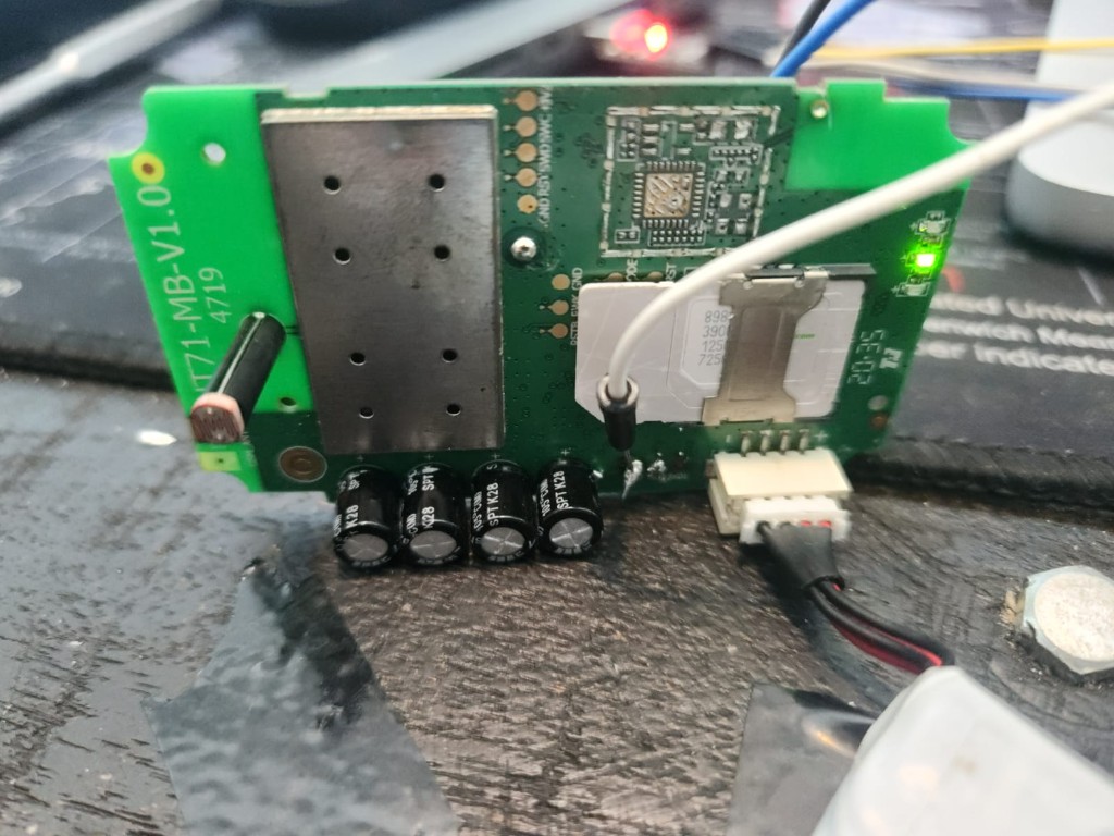
Main board (GT71-MB-V1.0.0): MediaTek modem under the large shield, SIM slot, and the SWD header (GND · RST · SWD · SWC · +3V) along the top edge.
- Large metal shield → MediaTek cellular modem / baseband (where
MAUI.11C…lives) - SIM slot, power connector, electrolytic caps
- SWD header:
GND · RST · SWD · SWC · +3V - Near SIM:
RST · TX · FWK · GND - Bottom UART:
TXD · RXD · GND← CP2102 wires (modem AT console)
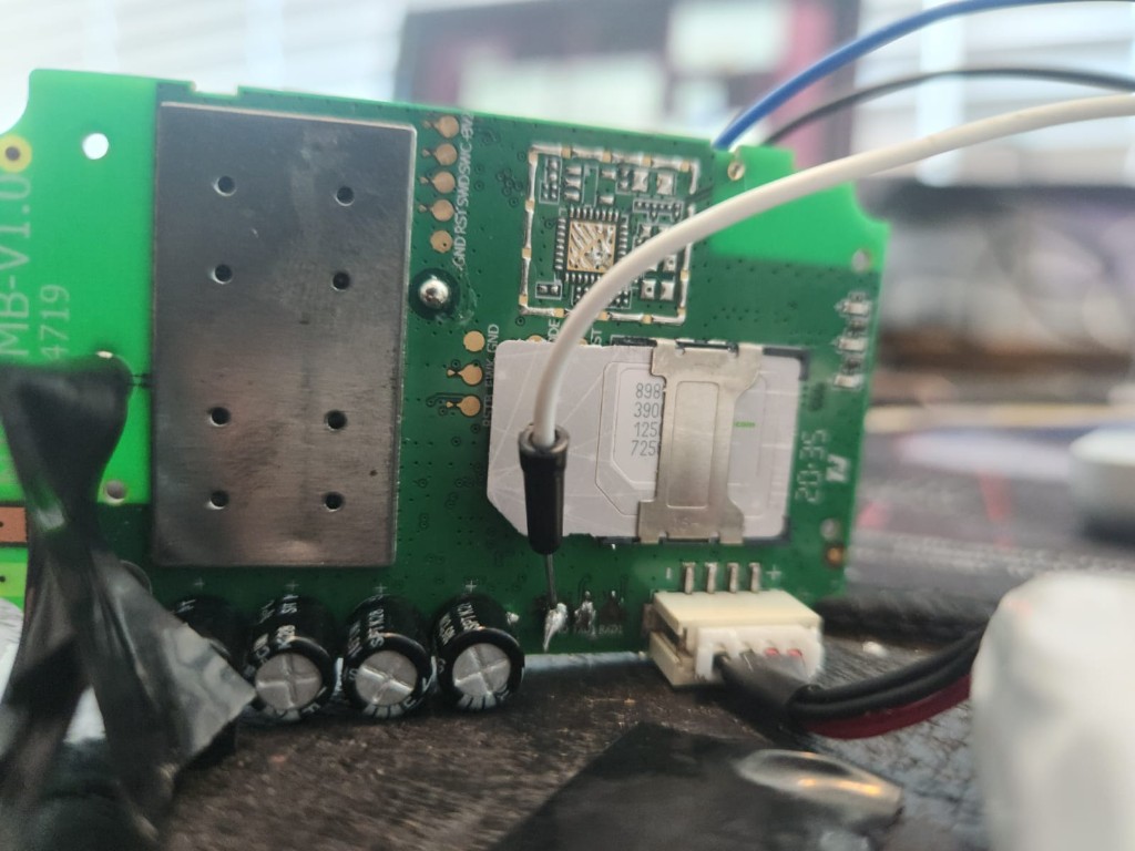
SWD header (top) and debug pads near the SIM — target for a Black Magic Probe dump of the application MCU.
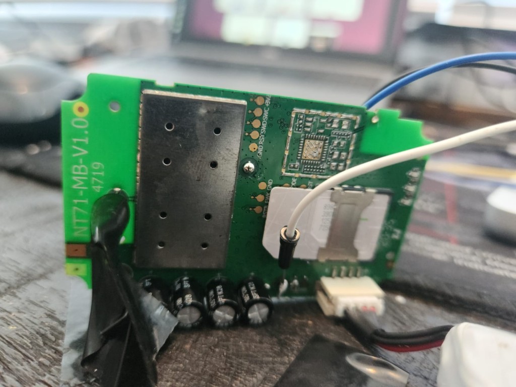
RSTB, FWK, and GND pads beside the SIM — short FWK → GND during power-on to enter MTK BROM/download mode for mtkclient.
Modem AT console wiring: white and black wires on the bottom TXD / RXD pads — connection that returned AT+CGMR at 115200.
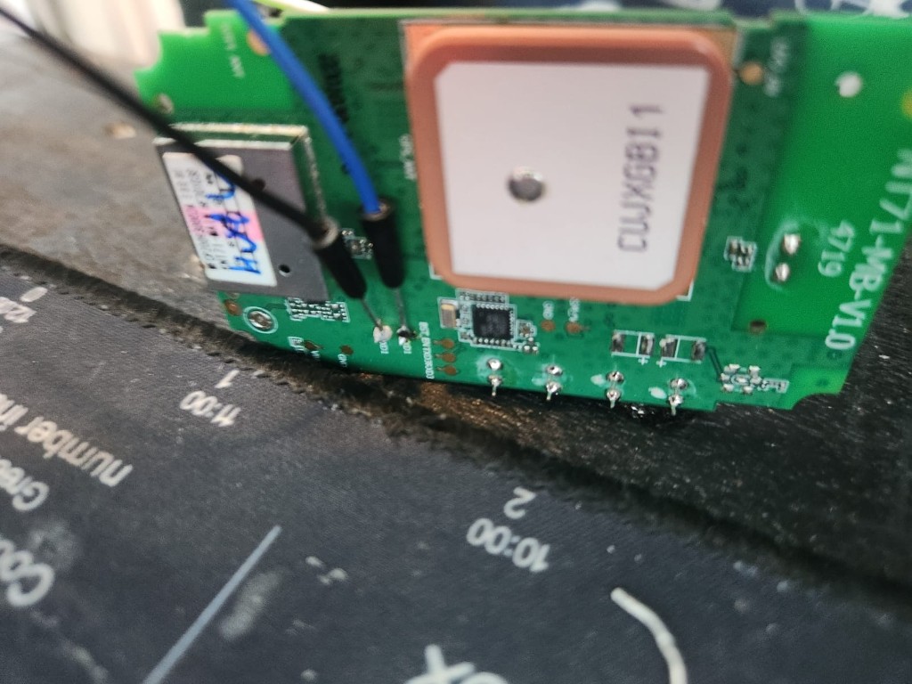
GPS daughter board — NT71-MB-V1.0
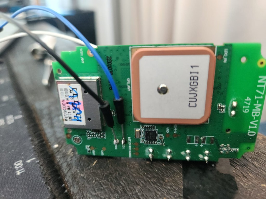
GPS daughter board (NT71-MB-V1.0): shielded NT71-MAIN module, ceramic GPS antenna (CUJXGB11), and UART pads along the bottom edge.
- Shielded module labelled NT71-MAIN (
WFCP200930002A,HF201030) - Ceramic GPS antenna (
CUJXGB11) - UART pads:
VBAT · GND · RXD1 · TXD1 · BST_EN · TXD3 · RXD3 · …
A complete backup means three targets:
| Target | Location | Likely tool |
|---|---|---|
| MTK modem + integrated flash | Under shield on GT71-MB | mtkclient over UART + boot strap |
| Application MCU | GT71-MB SWD pads | Black Magic Probe (e.g. WeAct Black Pill F411) |
| NT71 GPS / app module | NT71-MB UART + BST_EN | UART bootloader or mtkclient |
No single cable gets everything.
Act 5: You don't need Windows
Forum threads for MediaTek often assume Modem META or SP Flash Tool on Windows. The good news on macOS:
| Tool | Platform | Role |
|---|---|---|
| mtkclient | macOS, Linux, Windows | Full flash read on MT6261-class IoT chips: python mtk.py rf flash.bin --iot |
| Black Magic Probe | macOS via blackmagic / OpenOCD | SWD dump of application MCU |
gt710_probe.py | macOS | Metadata over AT (completed step) |
mtkclient on macOS (modem / main flash)
brew install macfuse openssl
git clone https://github.com/bkerler/mtkclient && cd mtkclient
python3 -m venv venv && source venv/bin/activate
pip install -r requirements.txt

# Enter download mode first (see below), then:
python mtk.py printgpt --iot --serialport /dev/cu.SLAB_USBtoUART --debugmode
python mtk.py rf gt710-mtk-full.bin --iot --serialport /dev/cu.SLAB_USBtoUART --debugmode
Entering BROM / download mode — try in order:
- Power off → short FWK → GND → apply power → run mtkclient → release when connected
- Power off → hold RST low during power-on
- Under the large shield: classic MTK test point (KCOL0 / COLO) shorted to GND during power-on
SWD with a WeAct Black Pill F411 (V2.0)
Flashed as Black Magic Probe (blackpill-f411ce):
| BMP (target side) | GT71-MB pad |
|---|---|
| GND | GND |
| PB9 (SWDIO) | SWD |
| PB8 (SWCLK) | SWC |
| PA5 (nRST) | RST (optional) |
Leave +3V disconnected if the tracker is already powered from its own connector.
Bench hardware verdict
| Board | Verdict |
|---|---|
| WeAct Black Pill F411 | Primary SWD probe after BMP flash |
| ESP-Prog | Useful as spare UART for mtkclient; SWD possible but fiddly |
| Arduino Nano (ATmega328) | No — no SWD, can't run BMP |
Recommended order of operations
1. gt710_probe.py          → metadata JSON (done)
2. mtkclient + FWK strap   → gt710-mtk-full.bin
3. BMP on Black Pill       → gt71-app.bin via SWD
4. BST_EN + RXD1/TXD1      → NT71 module bootloader hunt
Wiring reference (modem UART — what worked)
USB-serial RX  →  board TXD
USB-serial TX  →  board RXD
GND            →  GND
Do not feed 5 V from the adapter if the board has its own supply.
Status
| Extraction | State |
|---|---|
| Modem firmware version + IMEI/ICCID/SIM | ✅ Via AT / gt710_probe.py |
| Modem binary flash | ⏳ mtkclient + FWK/BROM strap |
| App MCU binary | ⏳ BMP + SWD on GT71-MB |
| NT71 GPS module | ⏳ UART + BST_EN bootloader |
| Concox app version string | ⏳ SMS VERSION# with working SIM |
Key Takeaways
- 115200 is correct for the GT71 modem AT UART; garbled output was boot noise plus the device polling its own modem.
- AT commands yield metadata only (
AT+CGMR, IMEI, ICCID) — not a flash binary; dump commands returnERROR. - The GT710 is two PCBs (
GT71-MB+NT71-MB) with three firmware stores; a full clone needs mtkclient, SWD, and possibly the GPS-board UART bootloader. - macOS works — mtkclient (
--iot) and Black Magic Probe on a WeAct F411 replace Windows META/SP Flash for most of the job. - Five PCB photos document SWD, FWK, UART, and GPS-board pads for repeatability.