How nRF24L01+ Wireless Module Works & Interface with Arduino
Source
- Type: webpage
- Origin: https://lastminuteengineers.com/nrf24l01-arduino-wireless-communication/
- Imported: 2026-05-20
- Figures: stored under
microcontrollers-and-socs/assets/lastminuteengineers-nrf24l01-arduino-wireless/(local copies).
Content
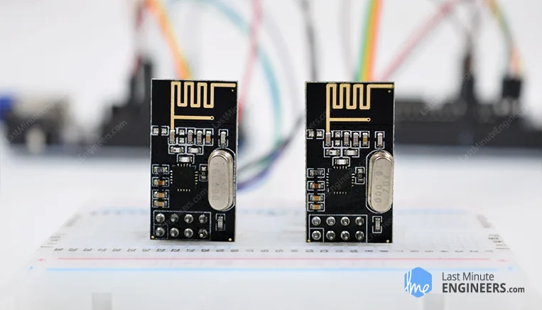
The nRF24L01+ transceiver operates in 2.4–2.5 GHz, supports 250 kbps, 1 Mbps, or 2 Mbps, and uses Enhanced ShockBurst (buffering, ACKs, automatic retransmit). Typical supply is 3.3 V only (do not feed 5 V on VCC); logic pins are 5 V tolerant on many modules. Power varies with mode (transmission currents are modest; standby and power-down are very low). Range depends on PCB vs PA/LNA, obstacles, bitrate, interference, decoupling, and supply noise.
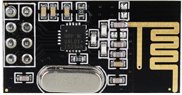
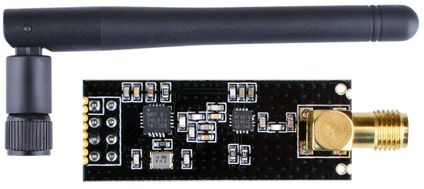
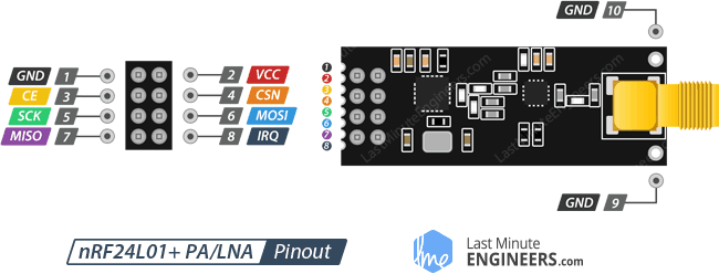
Two common hardware variants ship: integrated PCB antenna (shorter range) and PA/LNA plus external antenna (often marketed to ~1000 m LOS with caveats); they are broadly pin/interchange compatible where wiring supports both.
Technical specification (tutorial table)
| Item | Typical values |
|---|---|
| Frequency Range | 2.4 GHz ISM |
| Maximum Air Data Rate | 2 Mb/s |
| Modulation | GFSK |
| Max Output Power | 0 dBm (configurable negative steps) |
| Operating Supply Voltage | 1.9 V–3.6 V |
| Logic Inputs | 5 V tolerant (module dependent; always verify datasheet) |
For authoritative limits, rely on Nordic / module vendor datasheet.
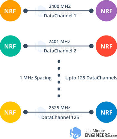
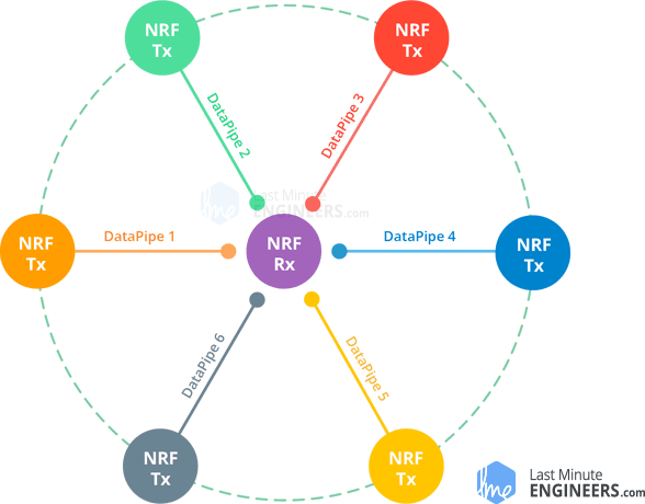
Channels and multiceiver
Logical channels occupy ~1 MHz steps across roughly 2400–2525 MHz ⇒ about 125 channels. Matching modules must share channel, bitrate, addressing/pipe conventions, etc.
Multiceiver: up to six pipes per channel (unique addresses); conceptual model is many TX → one coordinated RX.
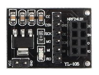
Pinouts
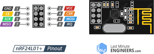
GND — ground (square pad marking on many breakout boards).
VCC — 1.9–3.6 V (tutorial also mentions up to ~3.9 V wording; defer to datasheet). Use MCU 3.3 V.
CE — chip enable (active high): controls TX/RX path timing in library usage.
CSN — SPI chip select (active low, idle high).
SCK, MOSI, MISO — SPI.
IRQ — active-low interrupt (optional in many sketches).
Wiring (Arduino hardware SPI UNO/Nano baseline)
Tutorial example uses:
| nRF24L01 | Arduino (UNO family) |
|---|---|
| GND | GND |
| VCC | 3.3 V |
| CE | pin 9 |
| CSN | pin 8 |
| SCK | pin 13 |
| MOSI | pin 11 |
| MISO | pin 12 |
CE/CSN can remap; prefer hardware SPI pins for bitrate headroom — follow your board’s SPI pin mapping.
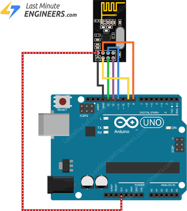
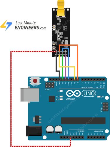
Duplicate the same wiring at both ends for paired TX/RX.
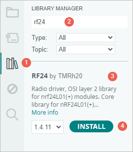
Libraries
Primary library in the tutorial: RF24 (TmRh20).
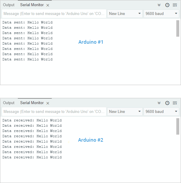
Example 1 — one-way "Hello World"
Transmitter:
#include <SPI.h>
#include <nRF24L01.h>
#include <RF24.h>

#define CE_PIN 9
#define CSN_PIN 8

RF24 radio(CE_PIN, CSN_PIN);

const byte address[6] = "00001";

void setup() {
  while (!Serial)
    ;
  Serial.begin(9600);

  radio.begin();
  radio.openWritingPipe(address);
  radio.stopListening();
}

void loop() {
  const char text[] = "Hello World";
  radio.write(&text, sizeof(text));

  Serial.print("Data sent: ");
  Serial.println(text);

  delay(1000);
}
Notes from the tutorial:
radio.write()acknowledges Enhanced ShockBurst behavior can block until ACK timeout / retries.- Practical payload cap 32 bytes per burst (library defaults must respect hardware FIFO limits).
write()returningboolcan reflect ACK success depending on ACK/auto-ACK configuration.
Receiver:
#include <SPI.h>
#include <nRF24L01.h>
#include <RF24.h>

#define CE_PIN 9
#define CSN_PIN 8

RF24 radio(CE_PIN, CSN_PIN);

const byte address[6] = "00001";

void setup() {
  while (!Serial)
    ;

  Serial.begin(9600);

  radio.begin();
  radio.openReadingPipe(0, address);
  radio.startListening();
}

void loop() {
  if (radio.available()) {
    char text[32] = {0};
    radio.read(&text, sizeof(text));
    Serial.print("Data received: ");
    Serial.println(text);
  }
}
Example 2 — struct payload (temperature + humidity)
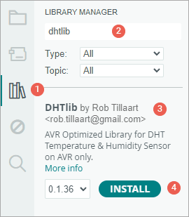
Adds DHT11 / DHTlib wiring on the transmitting side (DHTlib by Rob Tillaart: https://github.com/RobTillaart/Arduino/tree/master/libraries/DHTlib).
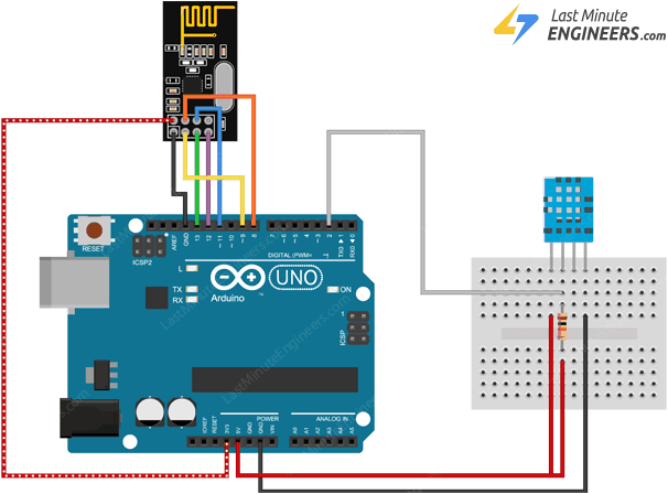
Transmitter (sensor side):
#include <SPI.h>
#include <nRF24L01.h>
#include <RF24.h>
#include <dht.h>
#define CE_PIN 9
#define CSN_PIN 8
#define DHTPin 2
RF24 radio(CE_PIN, CSN_PIN);
dht DHT;
struct SensorData {
float temperature;
float humidity;
};
SensorData data;
const byte address[6] = "00001";
void setup() {
while (!Serial)
;
Serial.begin(9600);
radio.begin();
radio.openWritingPipe(address);
radio.stopListening();
}
void loop() {
DHT.read11(DHTPin);
data.humidity = DHT.humidity;
data.temperature = DHT.temperature;
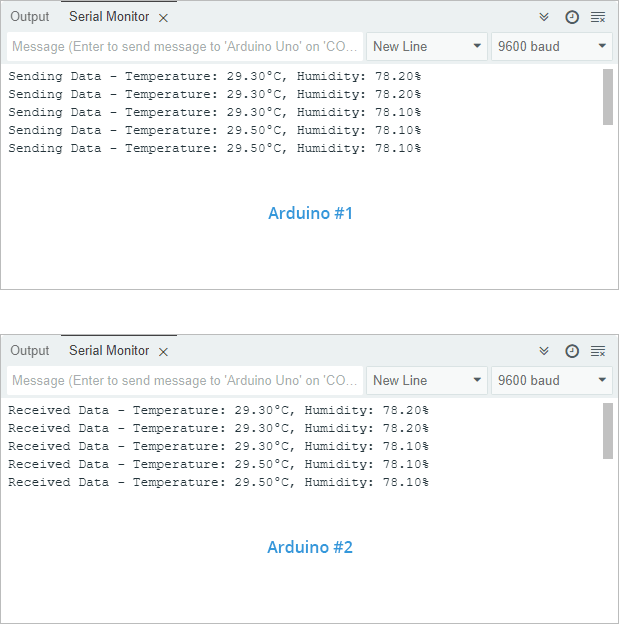
Serial.print("Sending Data - Temperature: ");
Serial.print(data.temperature);
Serial.print("°C, Humidity: ");
Serial.print(data.humidity);
Serial.println("%");
radio.write(&data, sizeof(data));
delay(1000);
}Receiver:
#include <SPI.h>
#include <nRF24L01.h>
#include <RF24.h>

#define CE_PIN 9
#define CSN_PIN 8

RF24 radio(CE_PIN, CSN_PIN);

struct SensorData {
  float temperature;
  float humidity;
};

const byte address[6] = "00001";

void setup() {
  while (!Serial)
    ;

  Serial.begin(9600);

  radio.begin();
  radio.openReadingPipe(0, address);
  radio.startListening();
}

void loop() {
  if (radio.available()) {
    SensorData receivedData;
    radio.read(&receivedData, sizeof(receivedData));

    Serial.print("Received Data - Temperature: ");
    Serial.print(receivedData.temperature);
    Serial.print("°C, Humidity: ");
    Serial.print(receivedData.humidity);
    Serial.println("%");
  }
}
Structs must agree exact layout on TX/RX MCU/compiler (padding/endian floats etc.) — same architecture is simplest.
Example 3 — bidirectional toggle (walkie-talkie sketch)
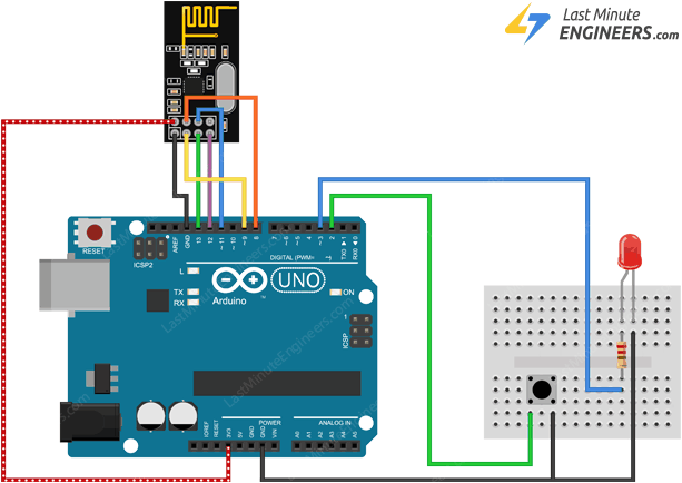
Adds momentary pushbutton + LED both sides — same sketch on both.

Sketch (copied verbatim from tutorial; debounced edge):
#include <SPI.h>
#include <nRF24L01.h>
#include <RF24.h>
#define CE_PIN 9
#define CSN_PIN 8
#define SWITCH_PIN 2
#define LED_PIN 3
RF24 radio(CE_PIN, CSN_PIN);
const byte address[6] = "00001";
int ledState = HIGH;
int buttonState;
bool lastButtonState = HIGH;
unsigned long lastDebounceTime = 0;
const unsigned long debounceDelay = 50;
void setup() {
pinMode(SWITCH_PIN, INPUT_PULLUP);
pinMode(LED_PIN, OUTPUT);
Serial.begin(9600);
radio.begin();
radio.openWritingPipe(address);
radio.openReadingPipe(1, address);
radio.startListening();
}
void loop() {
bool reading = digitalRead(SWITCH_PIN);
if (reading != lastButtonState) {
lastDebounceTime = millis();
}
if ((millis() - lastDebounceTime) > debounceDelay) {
if (reading != buttonState) {
buttonState = reading;
if (buttonState == HIGH) {
ledState = !ledState;
radio.stopListening();
radio.write(&ledState, sizeof(ledState));
radio.startListening();
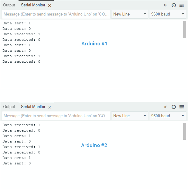
Serial.print("Data sent: ");
Serial.println(ledState);
}
}
}
lastButtonState = reading;
if (radio.available()) {
bool receivedState;
radio.read(&receivedState, sizeof(receivedState));
digitalWrite(LED_PIN, receivedState ? HIGH : LOW);
Serial.print("Data received: ");
Serial.println(receivedState);
}
}
Conceptual note: radios cannot transmit and listen simultaneously on chip — pattern is listen → briefly stopListening → transmit → resume listen.
Improving usable range / link quality
- Clamp supply noise: add adequate bulk / ceramic decoupling right at module VCC/GND footprint.
- Consider a regulated 5 V → 3.3 V adapter board integrating regulation + caps for cleaner supply when USB/bench rails are noisy.
- Channel choice: Wi-Fi often crowds lower MHz slots within 2.4 GHz ⇒ experiment with upper channel indices locally.
- Lower air data-rate ⇒ better sensitivity (tutorial cites −94 dBm @ 250 kbps typical vs −82 dBm @ 2 Mbps style trade — verify on your silicon rev / conditions).
- Higher TX power: use legal / thermal / battery budget appropriate setting (0 dBm max if device isn’t amplified module; PA/LNA parts add their own limits).
Cross-links from article: Nordic datasheet; Rf24 docs (https://tmrh20.github.io/); RFX2401C PA/LNA frontend cited for amplified modules.
Key Takeaways
- Treat VCC as 3.3 V-critical regardless of tolerant logic IO — browning-out or spikes collapse range.
- Common mode stack: SPI (
SCK/MOSI/MISO/CSN) +CE+ optionalIRQ; pair bitrate, channel, addresses/pipes. RF24patterns: TXstopListening()/write(); RXopenReadingPipe(...); startListening(); available/read.write()semantics intersect with ShockBurst/auto-ACK; design loops accordingly.- Struct telemetry MUST match exact binary layouts TX↔RX; mind padding & float endian.
- Range debug checklist: PSU decoupling, channel vs Wi‑Fi BLE overlap, LOS, bitrate, PA/LNA choice, antennas.